ROMERIN
ROMERIN
GENERAL DESCRIPTION
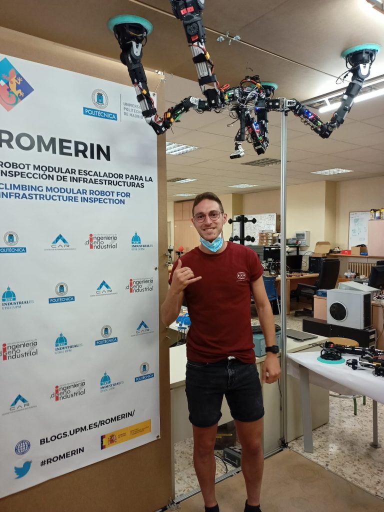
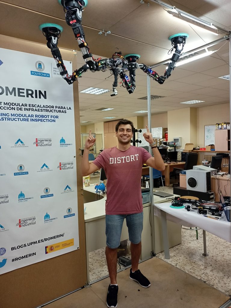
The modular robot, called as ROMERIN, is one of the most advanced prototypes of the ROMERIN project. It is based on the design and construction of a modular climbing robot, which seeks to imitate the anatomical structure of a human arm. Therefore, the robot has been designed with individual legs of 7 degrees of freedom: 3 in the shoulder and wrist and 1 in the elbow.

This robot is characterized by its great modularity because it is composed of independent and autonomous robotic legs from the point of view of processing, control and energy. Based on the requirements and functionalities of the robot, you must meet these goals:
- The system has to be resilient and fully modular, from an energy, mechanical and control point of view.
- Be able to share power with the other modules.
- Be able to adapt his structure efficiently climbing.
- Be able to function by itself; without external power.
- Be as light as possible and have an approximate size of 0.9 meters.
- STRUCTURE AND MATERIALS
The current version of the robot is formed by four legs attached to a body, whose structure is composed of two aluminum plates. These plates are strong enough to hold the legs’ weight and all the torsion forces that appear during the performance.
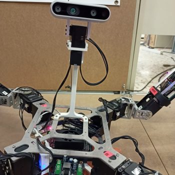
Within the body, a control computer is found, which communicates with the legs via Ethernet thanks to a security router placed on its side. Furthermore, a tension converter and a communication device are found for the control of the pan-tilt system. This system is responsible for controlling the position of the depth camera. Behind the lower plate, a battery is located to supply energy to the body electronics.
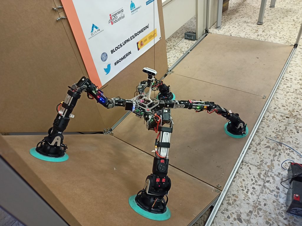
In a previous iteration, a temporary body capable of holding a variable number of legs was designed and constructed.
The structure of the body has a modular design composed of the rear and front, they have the capacity to accommodate 2 legs each, which are joined by metal bars. By extending the bars that connect both parts, it is possible to add intermediate modules to incorporate more legs to the body. Later, another more ergonomic support was designed for the robot, reducing the total weight of the system.

As for the materials, they can be divided into the metal bars of the modules and the plastic parts printed in 3D.
To determine the material of the bar several tests were carried out, depending on the requirements of torsion, bending and buckling. Finally, the aluminium profile was the one that best offered a weight/technical characteristics ratio. ABS was used to manufacture plastic parts using a 3D printer. This compound is extremely resistant and has a certain degree of flexibility, apart from that it can withstand different treatments such as polishing, sanding, painting, etc., maintaining a good surface finish.
- ENERGY SHARING
The robot’s greatest advantage is the ability to share energy between its modules in real time. To achieve this, a physical mean is used by which all robots can connect in order to import or export energy. It consists of a power bus with a voltage greater than that supplied by the batteries of the legs.
- Export hardware: Composed of a voltage booster to adapt to the bus voltage, a current limiter to prevent excess current to the bus, an anti-return diode to prevent voltage synchronization problems, and a “switch” to connect or disconnect all this hardware with the bus.
- Import hardware: This can be divided into two zones. The area in charge of bringing the voltage to the battery to charge it, passing through an intensity limiter so as not to damage the battery by means of an over-current; and the part that carries the direct voltage of the bus to the charge of the leg. In addition, both modes have a “switch” for the connection or disconnection to the power bus.

The import and export of energy cannot be activated at the same time, so a control and synchronization mechanism will be necessary to choose what you want to do depending on the state of the module.
- OPERATING MODES
Regarding th energy sharing, the robot operating modes can be divided into 4:
- Isolated mode: Predefined configuration in which the robot’s battery only feeds its circuit and engines, being galvanically isolated from the power bus.
- Power Sharing Mode: The battery powers the circuit and motors; in addition, it powers the bus giving a limited number of amperes.
- Charging mode: The power bus feeds the robot’s circuit and engines, and is also capable of charging the battery with current limitation.
- Damaged mode: If the battery is damaged, it is isolated from the circuit and it is the power bus that feeds the entire robot (circuit and motors).
In terms of communication, the use of wired tracks and wireless transmission are available in the robot. It should be noted that cable communication is more robust than wireless communication, but in the situation where the robot cannot physically connect to each other it will be necessary to have a non-wired medium.
For external communication between the modules, the implementation of the CAN protocol through wired media has been chosen. There is also internal communication between the microcontroller and the motors/sensors, for this two protocols, TTL and RS485 are used. The message from the engines is transmitted by both protocols, because the engines have their own identifier.
For aerial transmission media, two alternatives are used, Bluetooth V4.2 and Wi-Fi at 2.4 GHz. Both are included as standard in microcontrollers with wireless communication. These way of communication will allow a high data transmission.
- COMMUNICATIONS
- ACTUATORS
In the ROMERIN+ project it was decided to study the other variants that the actuators had to be electric mainly because of the cost and the favorable physical characteristics (size and weight). Within the electric actuators we find a great variety: DC motors, servomotors and motors step by step. Finally, the servomotors were chosen as the best alternative because both the reducer and the power and control electronics (feedback sensors) are integrated as standard, achieving a compact size.
The best alternative that met all the requirements were the DYNAMIXEL servomotors, the chosen for ROMERIN+ were: MX-106R, MX-64AT and XL-320.

ELECTRONIC DESIGN
- GENERAL ELECTRICAL SCHEMATIC
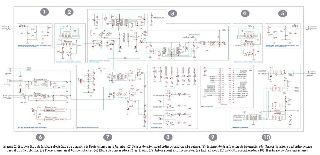
- ANALYSIS PARTS OF THE CIRCUIT
ENTRY AND EXIT PROTECTIONS
Section needed to protect the board at both the input and output the same circuit was designed to protect against the following phenomena:
- Over-intensity: protection composed of a fuse so that when the ampere limit is exceeded, the fuse is opened .
- Reverse polarity: contains an inversely connected diode so that in the event of a reverse connection of the battery/power bus the diode drives and causes a short circuit.
- Over-voltage: system composed of a tiristor and a zener diode connected inversely, will drive when between its terminals has a voltage equal to or greater than the rupture voltage which will cause a short circuit.

BIDIRECTIONAL CURRENT SENSOR
In order to know the direction of the current and the consumption mainly of the motors and the battery during the charge, two-way sensors were used at the entrance and exit of the circuit. This system consists of a shunt resistor, instrumentation amplifiers and a operational amplifier connected to a potentiometer to establish the reference voltage.
The consumption data is obtained as voltage in the resistance and is sent to the microcontroller, where the intensity consumption is obtained by means of the Ohm Law.

POWER DISTRIBUTION SYSTEM
This system consists of two electronic fuses (eFuse) responsible for limiting the current for the import and export of energy, it regulates the intensity that reaches the battery and the power bus. It is also composed of an incremental voltage converter whose function is to deliver a voltage to the power bus greater than that of the battery, so that in case of loss it can maintain a voltage level high enough for the charge.
In order to safeguard this system, protective elements such as capacitors are used to prevent electric arcs, fuses that protect against over-intensities and diodes that are inversely connected to prevent reverse currents.

SHORT CIRCUIT PROTECTION SYSTEM
This stage protects the engines from over-intensities. This operation is based on measuring the voltage drop in a shunt resistance by means of an instrumentation amplifier and then being compared with a reference voltage to determine if a short circuit is being produced. In case of detecting high intensity values, the relay in charge of isolating the engines will be activated.
Supercapacitors are not part of this system but their aim is to keep the voltage constant during conmutations produced in the energy sharing.

COMMUNICATIONS HARDWARE
The communications of the robot through wired routes are given by three hardware protocols, whose purposes are that the microprocessor has the ability to transmit and receive information from engines, sensors or other robots.
- TTL and RS485 protocols: Bidirectional communication between the micro and the motors based on a Half Duplex system. It consists of a bidirectional converter that adapts the logical levels of the signals and allows the data to flow in both directions, but not at the same time.
- CAN protocol: Bidirectional communication between the different legs based on a Half Duplex system. It contains a transceiver of the CAN bus capable of transforming the logical levels of the signal into voltage values and vice versa since the communication is based on a voltage differential between both lines.
ELECTRONIC REDESIGN
The new version of the ROMERIN electronics board is intended to replace the old model, maintaining the same functionalities and including a number of improvements. This, together with the fact that each of the boards forms an independent robotic module, will require the redesign of the electronic board to meet the following requirements:
– Simplification of the stages that can be established by other systems or simpler mechanisms maintaining the same performance.
– Dimensions and weight should be reduced as much as possible, achieving a better adaptation to the robot leg.
Before sending to manufacture the board, the 3D design was made using FUSION360. This program has been very useful for the organization and placement of the components on the PCB, since through the 3D models it is possible to check if there is any overlapping on the board.

Once the whole design process is finished, the board is checked to make sure that it is functional, for this purpose, the PCB design is sent to a foreign company to be manufactured.
As can be seen in the following image, there is a substantial change with respect to the size of one board and the other. Through the redesign, the length of the previous board was reduced by half, from 217 mm to 108 mm. The width is limited by the dimensions of the development board, so the dimensions remained the same.

In the control board redesign, it was decided not to implement the power sharing system on the board due to size issues. But with the modular extension, the robot regains the ability to share energy in real time. This property is reintroduced through an external module composed of the above-mentioned system.
The mechanism for distributing power is the same as the one used in the old version of the board. It is based on the power bus, whose purpose is to serve as a physical medium through which the robots can import or export energy.

